Manual of 3 Axis Brushless Gimbal Handheld & Multicopter use.
Thanks for purchasing our 3 Axis Brushless Gimbal. Please read this manual carefully. In that we have no control over the correct use, installation, application, or maintenance of our products, no liability shall be assumed nor accepted for any damages, losses or costs resulting from the use of the product. Any claims arising from the operating, failure or malfunctioning etc. will be denied. We assume no liability for personal injury, property damage or consequential damages resulting from our product or our workmanship. As far as is legally permitted, the obligation to compensation is limited to the invoice amount of the affected product.
Features:
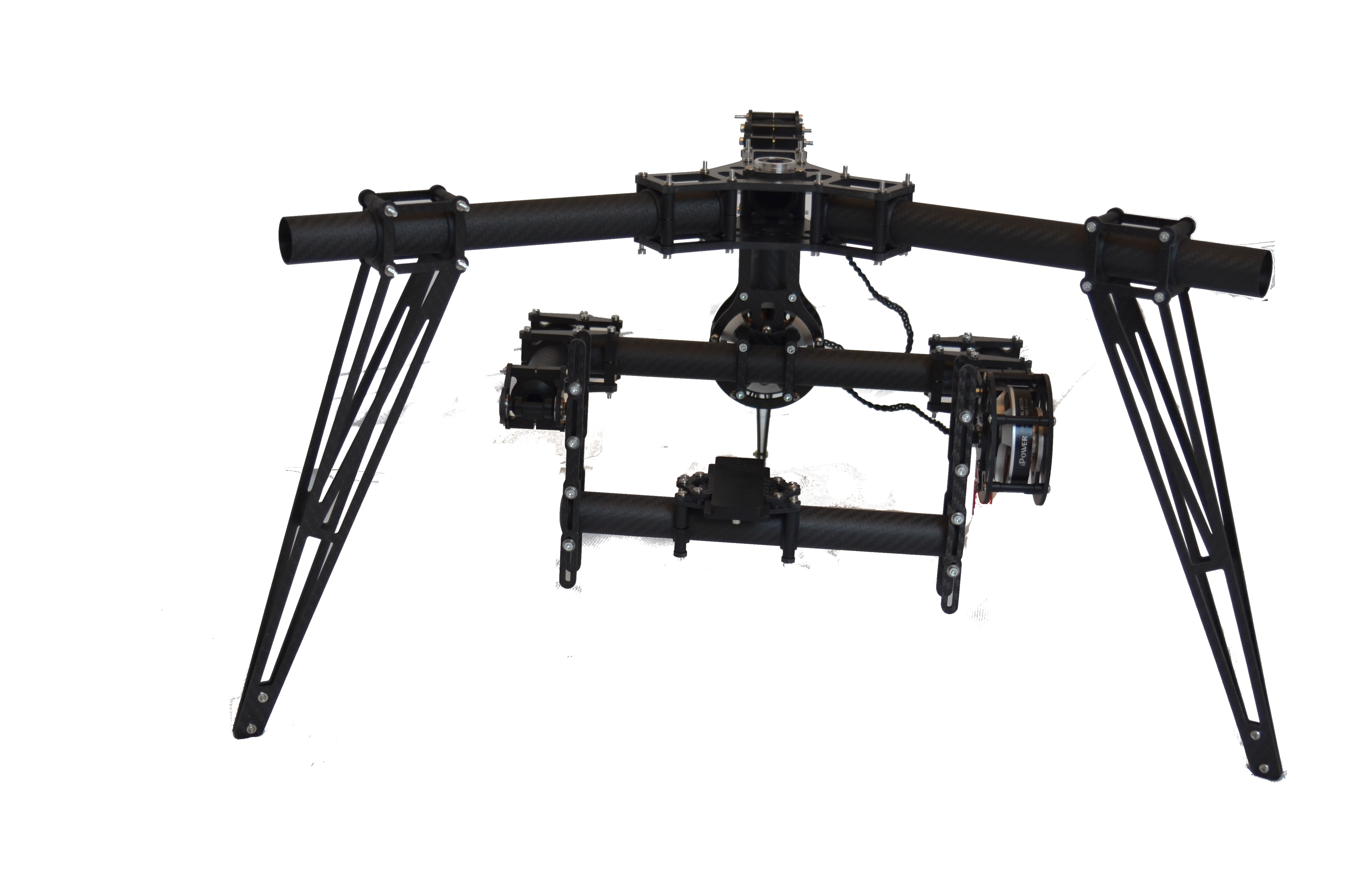
CINESTAR, Droidworks, Hoverfly, Microcopter 3 Axis Brushless GIMBAL system & Steadicam
This Gimbal will fit Cinestar, droidworks, hoverfly with no modification & work with any large multi rotor that will lift 25lb an more.
1. 3 x 5208 motor that will lift up to 10lb
2. Bearings on all 3 Axes Pitch, Yaw & Roll
3. Gimbal 60 degree on Roll axis left right (can be modified)
4. Gimbal 360 degree on Pitch axis left up down
5. Gimbal 360 degree on Yaw axis around
6. Landing gear with motor cage in the Center hub including barins fit 5208/5206 motor
7. Compatible with all 2 Axis, 3 Axis Brushless controllers
Specification:
wayes under 1000kg, 4mm 3k Carbon fiber Matt, 25mm 3k Carbon Fiber tube Matt, height , width, length, color black
motors Specification:
Model NO.: GBM5208-150
Weight:168g
Motor Dimensions:63x25mm
Stator Dimensions:52x8mm
Copper wire(OD):0.27mm
Configuration:12N14P
Resistance:10.2 ohms
Wind type and termination method:Star style
Pre-wounded with 150 turns,5.0mm shaft
Flexible Mounting Holes:
Bottom mounting holes: (3 holes) 32mm center to center,(4 holes)25mm center to center
Top mounting holes: (2 holes)12mm center to center,(3 holes)17mm center to center
force applied : 600-1500g
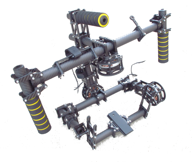
Begin To Use Your New Brushless Gimbal:
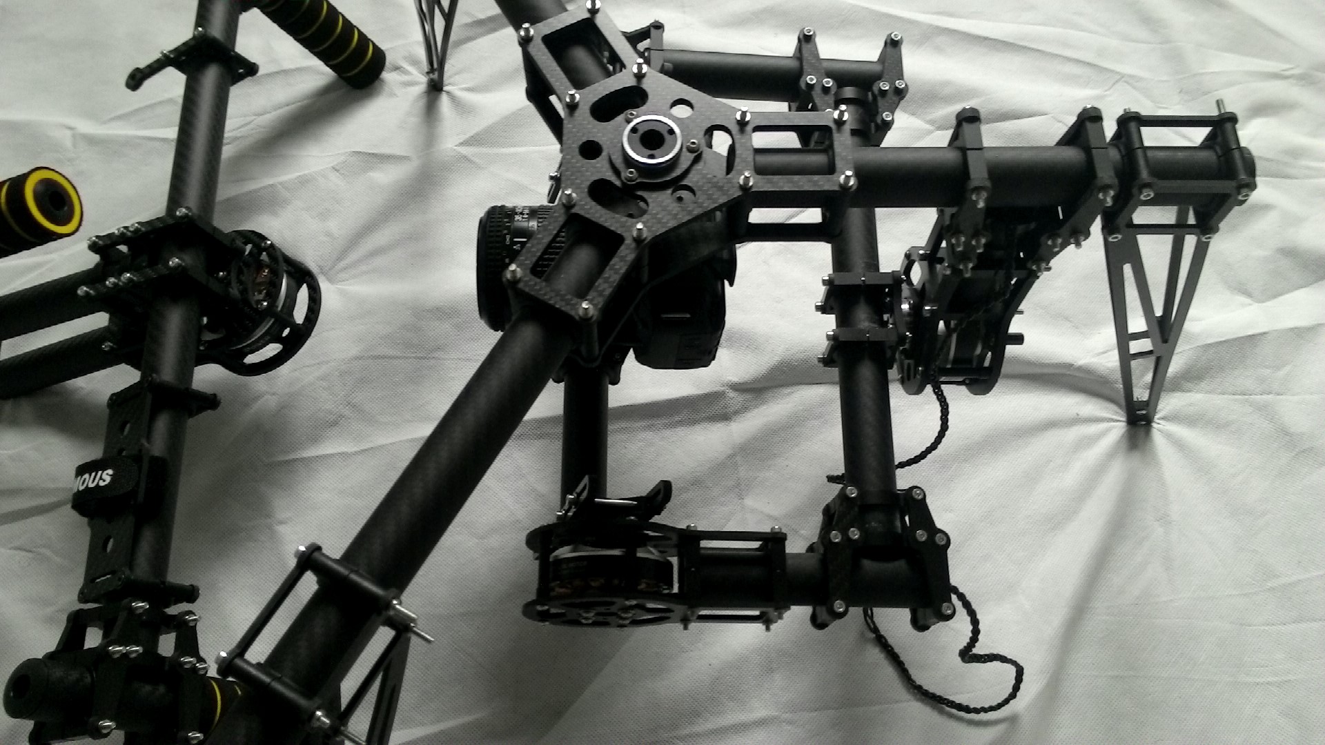
1. Assembly
Put parts together do not tighten the clamp bolts are facing upwards press nuts downwards except for center cage of the landing gear.
2. Fitting should be loose You will tighten after adjusting the parts to level "using a level" in X and Y axis. After you find the level point hold it and tighten the 25mm clamps till joint no longer moves. All Joints must be level on there own plane.
Set up for use:
1. Find the center of gravity
Move the camera tray assembly to the center of the frame , attach camera.
Move rear tray assembly left to right until is balanced (not tilted toward the ground left or right on the Roll Axis) not touching the ground on either end of the camera tray. when you're happy tighten the clamps on rear Roll assembly.
2. Balancing the camera Roll
Move the camera forward or backward in its tray until it is balanced with the tilt Axis at 90 degrees or as much as possible. when you're happy tighten the clamps on Tilt Axis assembly & camera tray.
3. Balancing the camera Tilt
Your Camera should be balanced, it should not tilt left or right up or down when you position the camera in it's tray.
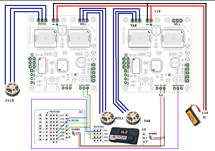
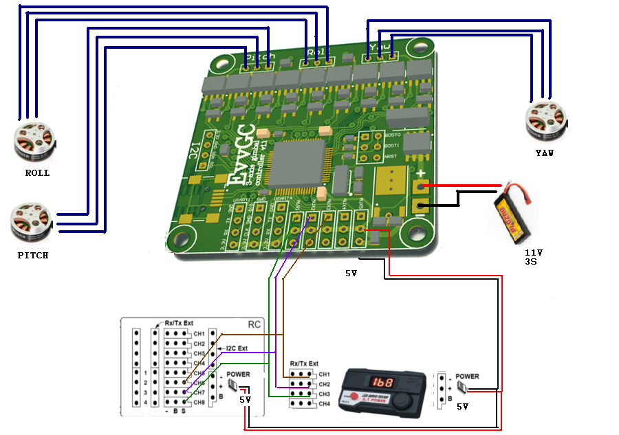
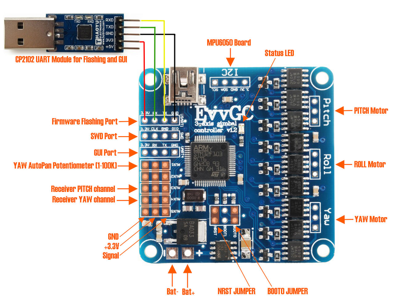
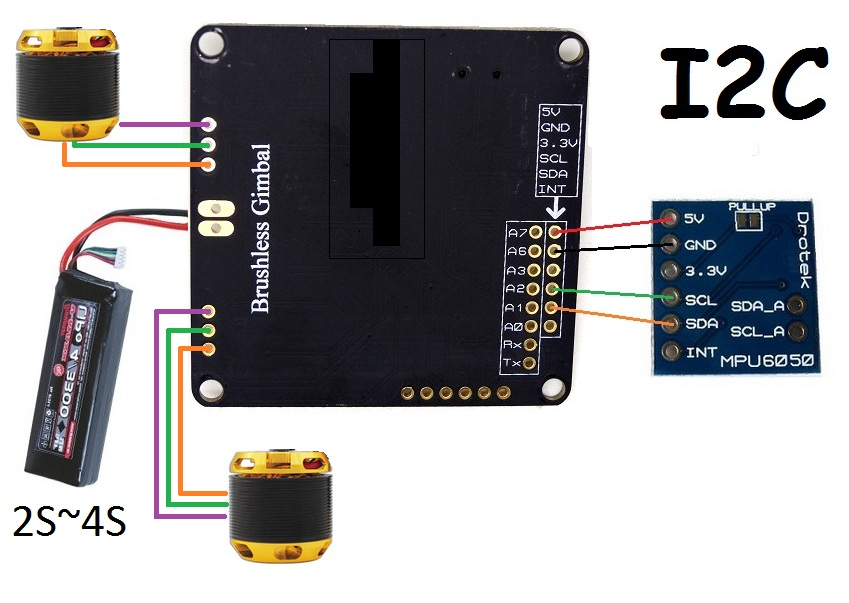
Connecting the controllers:
Software Additional resources:
Martenez:
-1?The source code:
http://code.google.com/p/brushless-gimbal/downloads/detail?name=_043_A.rar&can=2&q=
-2?Debug software and firmware download:
http://code.google.com/p/brushless-gimbal/downloads/list
-3?USB computer driver download:
http://www.ftdichip.com/Drivers/VCP.htm
-4?The motor information:
http://www.simplebgc.com/electronics/motor_rewind/
-5?Detailed information, please understand the website:
http://code.google.com/p/brushless-gimbal/
Martinez-Manual:
http://mymobilemms.com/Martinez-Manual.pdf
- EvvGC 3/2axis Brushless Gimbal Controller (Open Source)